Here is an example of a ladder logic program that controls a simple traffic light system:
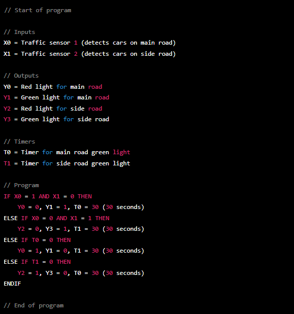
This program uses two inputs (X0 and X1) which are connected to traffic sensors that detect cars on the main road and side road. The program also uses four outputs (Y0, Y1, Y2, Y3) which are connected to the red and green lights on the main road and side road. The program also uses two timers (T0 and T1) which are used to control the duration of the green lights on the main road and side road.
The program uses a set of IF-ELSE statements to control the traffic lights based on the inputs from the traffic sensors. If cars are detected on the main road and no cars are detected on the side road, the program turns on the green light for the main road and starts the timer T0 for 30 seconds. If cars are detected on the side road and no cars are detected on the main road, the program turns on the green light for the side road and starts the timer T1 for 30 seconds. If the timer T0 reaches zero, the program turns on the red light for the main road and the green light for the side road, and starts the timer T1 for 30 seconds. If the timer T1 reaches zero, the program turns on the red light for the side road and the green light for the main road, and starts the timer T0 for 30 seconds.
Please note that this is a very basic example and in real life a lot more factors and safety measure needs to be considered.
No comments:
Post a Comment